
Here to reader five technical ideas are submitted:
1. A mode, which will allow
to adapt for work in high vacuum of the manipulator actually any design.
2. A mode, which will allow very quickly to receive high vacuum.
3. A mode, which will allow to make thick products from amorphous metal alloys (The note: The this mode still requires of the experimental check)
+ The method of improvement of the 3D printer, which is destined for creation of metal products (possibly by means of this method we can receive volumetric products from amorphous metals)
4. The room superconductivity (The note: The this mode still requires of the experimental check)
I hope, that the specified modes will interest experts in the given domains. And after acquaintance with them readers
with big trust will consider a possible mode of the decision of a problem of controlled nuclear synthesis with the help of the phenomenon cavitation, described on my site.
In modern science-intensive industries often it is necessary to carry out technological operations in high vacuum.
Thus there is a problem of a manipulation by the subjects, placed in high vacuum.
For example, it is necessary to move substrates on which make the evaporation.
Extremely irrationally after evaporation of each substrate break impermeability of the vacuum technological
chamber and manually to move substrates, and later again to receive high vacuum. It would seem, the given
problem can be solved by means of the mechanical manipulators, capable to move subjects in vacuum arbitrarily
without infringement of impermeability of the technological chamber.
However usual electronic-mechanical manipulators for these purposes is unsuitable - in high vacuum there is a mutual
rubbing of a details of joints of manipulators and, finally, their reciprocal wedging. It is possible to prevent similar
rubbing and wedging of joints of manipulators if to enter into them the liquid greasing. But the lubricant by evaporations
"envenom" of the high vacuum. Thus, we have collided would seem, with a unsoluble problem: if we not make greasing of
joints of manipulators, then we can not prevent their breakage in high vacuum, but at use of the lubricating liquid we not
can receive high vacuum.
About this problem I have learned when I was the schoolboy, in the seventies, from article, printed in the Russian
magazine " Young technician ". Unfortunately, now I do not have this magazine, and moreover after so many years I
now already do not remember its number. I can tell only, that this article has been printed in one of three numbers
of magazine either number 3 for 1977, or number 5 for 1972, or number 9 for 1972. In the presence of the very big desire the reader
of the my Web pages can familiarize with this article, if he will glance on a new Web site of editorial staff of
magazine "Young technician" and will order there at one's own expense of the DVD disk, where be numbers of
magazine of all the last years.
To the same readers of mine Web page, which will decide to save money, I can shortly retell the contents of the
article. In article not only the problem of a manipulation by subjects in high vacuum was described, but also the
way of its decision was considered - the one soviet inventor has suggested to apply pneumatic manipulators, which
at all have no joints.
This inventor wanted to carry out the moving of subjects in high vacuum by means of the metal thin-wall
tube-membrane, which can change the own geometry under action of injected in her of gas (how it occurs
in a mechanical manometer with the Bourdon tube).
Already then, in 70-s years, at reading this article it seemed to me, that
similar, exceptionally pneumatic,
manipulators will not provide necessary accuracy of moving of subjects in vacuum and consequently will not allow
to automate industry to the full.
Thirty years ago I have thought, what will be more correct for the decision of a problem to use some other approach.
However at that time I was the schoolboy, and I did not have an opportunity to patent the idea.
In my opinion, this idea till now has not lost the topicality. In the Internet I have seen a great deal of the Web
sites of the leading firms, engaged vacuum technologies, and I can assume, that, despite of the certain progress in
the field of the vacuum technologies, the problem till now is not solved to the full.
Therefore I expound on this Web page the own idea.
Now we shall consider a way, which will allow to solve this problem:
"The method of Streltsov's of protection against aggressive influence of vacuum of the joints of
mechanical manipulators, intended for fulfillment of technological operations in high
vacuum".
The specified method is shown on the drawing 1.
Drawing 1.
The details of joints (1) mechanical manipulator (2) are abundantly lubricate by lube. Later, on the manipulator put on a continuous elastic cover (the "skin") (3), which will share all the volume of the vacuum technological chamber into two unequal parts. Inside the continuous elastic cover (the "skins") we put the mechanical manipulator, with the joints, which be lubricate by lube. On the outside of the continuous elastic cover (the "skins") there will be the whole of other volume of the technological chamber, in which it is necessary to receive high vacuum. The fore-vacuum the pump (4) in process of evacuation of gases will create gas discharge simultaneously on each side of the continuous elastic cover (the "skin"): as in main technological volume of the vacuum chamber, as well as and in internal volume of the continuous elastic cover (the "skin"). For that from fore-vacuum of the pump go two pipes, one: (5) goes to the IPS, which is connected to the technological chamber, other pipe: (6) is connected to volume, which made into inside volume of the continuous elastic cover (the "skin"). The fore-vacuum the pump (4) in process of evacuation of gases will create gas discharge simultaneously on each side of the continuous elastic cover (the "skin"): as in main technological volume of the vacuum chamber, as well as and in internal volume of the continuous elastic cover (the "skin"). For that from fore-vacuum of the pump go two pipes, one: (5) goes to the ion pump, which is connected to the technological chamber, other pipe: (6) is connected to volume, which made into inside volume of the continuous elastic cover (the "skin"). Thus, inside of the continuous elastic cover (the "skins"), will be low vacuum, which is poisoned reeks of greasing of the joints of the mechanical manipulator, but on the outside surface of the continuous elastic cover (the "skins") we will having the high vacuum, in which with help of the "covered" manipulator it will be possible to make moving of objects, necessary for fulfilment of technological process. The unimportant by a pressure of low vacuum (10-3 mm. of mercury), caused by evaporations of greasing, will compensated by the forces of elasticity of a material of the continuous elastic cover (the "skins").
(It is necessary to notice, that the offered method has the prototype,
which already successfully working many years, it - spacesuit, basically consisting of
elastic polymeric materials. But inside a spacesuit the pressure is created much more:
near 760 millimeter of mercury, i.e. pressure difference on the different sides of an
covering of a spacesuit approximately in 700000 times more, than in a method of protection
of the manipulator, which is considered here. And it does not create of the big problems
with inflating the covering of a spacesuit. Therefore is possible to believe, that there
will be no problems and with ballooning a protective covering and at the offered method of
protection of joints of manipulators. Though, certainly, a protective covering, in some,
but is essential smaller, degrees will constrain movements of the manipulator as well as
the spacesuit constrain movements of the cosmonaut but to work the offered method all the
same will be.)
On a surface of a protective covering it is possible to put of the corrugation, then the
covering can be not only from the polymers, but also from the metal. Anyway, but such
corrugated surface it can be made on an covering in the locations of joints of the
manipulator.
On the drawing 2 show the similar classical corrugated surface, which be put on a
cylindrical surface. Received the thin-wall product reminds the sylphon. But similar
classical corrugated surface will allow to make only bending of joints of manipulators,
i.e. movements, which remind of the bendings by the person of a elbow joint.

Drawing 2.
On a drawing 2 the directions of a possible flexion-extention movements are shown by arrows.
� B
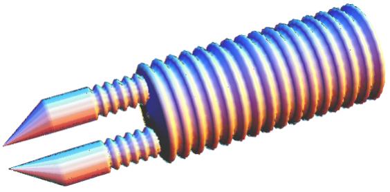
In this case the corrugated surface should have of the spiral winding - how you can see on a drawing 3. Drawing 3.
On a drawing 4 is represented the axonometry of a similar product - a part of a protective covering with a corrugated
surface, which have of the spiral winding. Arrows on a drawing 4 show possible the rotary movements with limited by
the amplitude of a joint of the manipulator, with an protected surface of such type. Thus the spiral corrugated surface
also can allow of the flexion-extention movements, how be designated by arrows on a drawing 2. I.e. the spiral
corrugated surface will provide more of the degrees of freedom of a joint of the manipulator: as flexion-extention
movements, so and rotatory motions. Therefore there can be more expedient, if we entirely the all manipulator
protectes in covering, with spiral corrugated surface, that will provide the best mobility of a hand of the manipulator.
Thus on a protective covering of manipulator can be the separate sites with spiral corrugated surface, with different
directions of winding. Drawing 4.
Fingers (mechanical gripper) of the manipulator intended for work in high vacuum, also are protected from aggressive
influence of vacuum by a protective covering, you can see drawing 5 where the is schematically shown the "didactyle
glove". Thus corrugated surface must be put in the locations of joints of "fingers" of the manipulator.
Drawing 5.
The note: in those places where the manipulator have of a contacts with the relocatable subjects, from above the
protective surface we can established of the high-strength superimposed elements which will prevent wear of a
protective covering. Drawing 6.
The coordinate table fastens to the central part of this membrane. In result we receive an opportunity of moving of him in flatness, parallel to a membrane. As well as earlier with one side of such membrane there will be a low vacuum and the mechanisms plentifully greased, which is providing moving of a coordinate table, on other side of the membrane - the himself coordinate table, which be in high vacuum. Probably as to do on a membrane the corrugated surface not as concentric circles, but as the spiral of Archimedes - then the coordinate table can be rotated on small corners. Drawing 7.
In addition to all, what I told, it is possible to use the sensor for measuring a difference of pressure inside and outside of a protective covering. On the basis of measurings of this sensor will be possible to more correctly adjust with the help of automatics of the work of gas-mains, both during getting of high vacuum, and during a raising in the working chamber of pressure up to atmospheric.
For getting of high vacuum apply two pumps: mechanical (so-called forevacuum) the pump, he creates preliminary the
discharge in a pumped volume to the tenth shares of millimeter of a mercury. Then, after that as effectiveness of
work by the fore-vacuum pump will decrease because of achieved discharging, the basic role in eviction of the residual
gases pass on to the oil-vapor pumps or, in rare cases, to the getter-ion pumps or
to the turbo-molecular pumps. The existing
the getter-ion pumps have doubtless advantages: in the high speed of eviction of the residual gases, quality of received
vacuum. However they have also and lacks - complexity of a structure, necessity of use for sprayed the reagents Ti, Mo,
Zr... Probably for these reasons they can not on equal compete with a diffusion pumps and as consequence they concede to
the last by the prevalence. (Confirmation to that can be even a brief article, published in magazine " the Science and life" 9 for 2007). Drawing 8.
The pump is connected to a vessel, in which create the vacuum, with help of the manhole (1), which, as well as basic casing (2) by a pump's is carried out from the dielectric. The molecules of gas, which we by deflate, accidentally fly into space (3), on the sides of which be placed two metal grids - electrodes (4) and (5) . Besides in the pump be two metal funnels-electrodes ( the infundibulums), (6) and (7), which by the wide basis (bellmouth's) rest on grids - electrodes (4) and (5). Spatially the funnels-electrodes (6) and (7) be coaxial situated, so, that them the wide basis (bellmouth's) have opposite direction: one to another. Narrow finiteness of funnels ( the infundibulums) are a bent, and to them be joined of pipes (8) and (9), which done from a dielectric of a material, other ends these the dielectric pipes are connected to the preevacuation pump. Drawing 9.
But here, in process of evacuation of the vestigial gases it is necessary to switch polarity of a source of a voltage by the special permutator (2), on a drawing he (the permutator) is designated by a means traditional for the electrical engineers, thus, that: at high pressure of gases, the funnel should have positive potential with respect to a electrode-plate, but at low pressure of residual gases - the funnel must have the negative potential. (Other details, which used on this drawing, be same how and on a drawing 8.) As against an earlier considered design of the pump with two funnels in such simplified pump there is not danger of gyration of ions on a closed circle.
Drawing 10.
Thus the pump speed of the gases from the technological chamber very strongly will increase, and the general time, spent
for creation of the high vacuum, accordingly decreases.
Then, when we achieves of the high vacuum in the technological chamber, it is possible to switch off of the glow discharge,
which be in all volume of a vessel and to include for maintenance of the achieved quality of vacuum of the separate IPS,
located from limits of the technological chamber, or we can use of the traditional local of the getter-ion pump.
No other pumps (oil-diffusion pumps, getter-ion pumps, turbo-molecular pumps) allow to receive such high of the pump speed of the gases from
the technological chamber. Really, if to try to make the technological chamber as internal volume of the steam-oil pump,
then all space of the technological chamber will be poisoned with pairs oils. If to try to transform the technological
chamber in internal of the volume of the getter-ion pump, then in internal space of the technological chamber it is
necessary to spray sorbents: Ti, Mo... But the sorbent also pollutes the working chamber - he can be by a harmful
impurity for technological process which we are going to carry out. And, besides, the all other pumps is much more
complex in exploiting (for oil-vapor pumps, for example, always there is a danger, what the lube will be splashed
out in the technological vacuum chamber), therefore it is probable, what the rather widespread the oil-vapor pumps
in the near future will be superseded in the industry and laboratories by ionic pumps of Streltsov's.
Drawing 11
The researchers already some decades scrutinize of the metal alloys, with the amorphous atomic structure, which received
by superfast cooling. These materials have unique magnetic, strength properties and anticorrosive properties. For the
first time about amorphous metals I have learned in 1980, having read article in magazine
"Young technician" number 11. For these years nothing has changed. As and before, the
researchers can receive products from amorphous metals as well as 25 years ago only as a powder,
a thin foil, or a thin thread. Drawing 12
On a drawing 12 how a number 1 is designated the crucible with hot a molten by metal , which we will coat on a nitrogen-cooled base sheet (is designated on drawing how number 2). The ultrasonic vibrator 3 informs oscillatory movements to the crucible , in which be hot a melt metal's, . How consequence, the hot molten metal will atomise on the small droplets. Between crucible and base sheet create a high difference of electrical potentials. Thus what vibrating crucible, with hot a melt metal, is connected to a positive pole of a source of a high voltage, and base sheet - to a negative pole. Overwhelming number of droplets precipitable of metal, received with by means of the ultrasonic atomization will have positive electric charge owing to loss of electrons because of a thermoemission effect. Under the action of an electrical field, existing between a base sheet and crucible, positively electrically loaded droplets of metal will get velocity in the direction of a base sheet, where they and will be precipitate (adhere). 1.
To her (on her surface) we sprays a metal covering, i.e. she forms the basis (or form's for the future product made from the amorphous metal), 2.
Substrate serve how the tankage (how a volume) for liquid air.
3.
Substrate have use how a wall for the chamber, in which in high vacuum we carry out spraying of metal, i.e. on the one hand of a base sheet be a vacuum, on the other - normal atmospheric pressure.
The offered mode of creation of metal coverings has several advantages: Drawing 13
However at us can arise the need(requirement) that the hand of the vacuum manipulator would make the rotary movements similar to those movements, with limited by angular amplitude, which the person makes, twisting the screw by a screwdriver (see drawings A and �).


I shall dare to assume, that the way of protection of electro-mechanical manipulators, considered here, by means their
placing in the protective goffered cover, has not lost the topicality, even in spite of the fact that presently exist
and a solid lubrication (molybdenum disulfide), which does not give evaporations.
Would seem, simply enough lubricating by such solid lubrication of joints of any first electro-mechanical manipulator,
which we has got under a hand, and he at once will be suitable for work in high vacuum. Because such solid lubrication
does not give evaporations and at the same time prevents pinching of joints. However this opinion is erroneous.
We should understand, that the manipulator is supposed to be used in enough hostile environment - in high vacuum for
realization of technological operations. Furthermore the technologists often enough for improvement of quality of vacuum
before execution of technological operations make the warming of the vacuum chamber up to 100 - 200 0 C. During
such warming up the electronics of the usual manipulator can break. Besides during realization of technological
operations (covering or ionic etching) the mechanisms of the manipulator also can suffer. Therefore, not looking at
existence of solid lubrication, use of the protective corrugated metal tubular cover is quite justified.
Firstly, the protective corrugated metal tubular cover will allow to adapt for work in vacuum the manipulator practically any design.
Secondly, the tubular cover will protect electronics of the manipulator from strong warming up - because the internal volume of a protective tubular cover before will be "filled" by vacuum, so the original "thermos" will formed. Because of absence of the gas convection the protective tubular cover can be strong enough heated, while the manipulator inside it protective tubular cover remains cold.
Thirdly, the corrugated tubular cover will protect mechanisms of the manipulator from the technological processes occuring inside of the working vacuum chamber.
(Here also I consider necessary to note following circumstance: I already was writing, what I have seen enough plenty
Web pages of the leading firms, engaged by the vacuum technologies. And I had an opinion, what only the manipulator "MEM - 10 - SDG"
Institute of physics of the high energy can make a competition to the way, offered here. It is a single design of the manipulator, capable is nice to work in
high vacuum. The executive mechanism of this manipulator at all does not contain electronic components, therefore
he is not afraid of heating. But it is valid unique, and, hence, dear the device. While the use of the protective
corrugated metal tubular covers allows to us simply and cheaply accommodate for work in vacuum the manipulator actually
any design.)
A protective surface as membrane, with radial corrugated surface, we can use for moving in the high vacuum
of the coordinate table, how you can see on a drawing 6.
Unfortunately, the such mode, with the corrugated surface as the spiral of Archimedes, may be used for turn of a coordinate table only on the small corners, just as spiral corrugated surface allows to carry out rotation of a hand of the vacuum manipulator only on the limited corners. In this connection it is possible to offer one more variant of protection against high vacuum of the mobile joint, which providing an opportunity of turn of a joint of the manipulator or a coordinate table on any corner without pollution of vacuum by the vaporizations of the greasing. But this mode will be described below, since I believe, that to reader previously follows will familiarize with the device of the ion pump of Streltsov's.
For technological service (repair) of the similar manipulators, protected by an covering, in the equipment it is necessary to provide a mode of a raising of pressure up to atmospheric. And what is very important: to carry out increase of pressure necessary simultaneously with identical speed with both sides of the protected covering so we can prevent its damage. For this purpose it is possible to use the special faucet. As a matter of fact in this design on one axis should be placed a two cranes similar how to samovar, you can see drawing 7. Then by the turn of one handle it is possible to open two gas-mains simultaneously. One gas-main allow access of atmospheric air to one side of a membrane another - other gas-main to another side of membrane. The cross section of gas-mains the miscellaneous, their ratio select same, as the ratio of volumes on the different sides of a protective membrane.
Certainly, proposed here the method of protection of the joints of manipulators from aggressive influence of high vacuum is not deprived of lacks - the protective covering by own elastic properties will impede for the movements of joints of manipulators, corners of a bend of joints are limited at the size (so as not tear an covering). But nevertheless the considered here a means allows to find quite acceptable decision of a problem of manipulation with subjects in high vacuum.
The ion pump of Streltsov's
In this part of my article there will be a speech about an opportunity of replacement of the oil-diffusion pumps and the getter-ion pumps on the ionic pumps special designs. At first sight to experts can seem, what the speed eviction of the proposed pumps below, than at already existing the getter-ion pumps. But it only at first sight.
In reality the productivity of described pumps in some technological processes will be much higher, than at all existing pumps.
The general design of the ionic pump of Streltsov's (further I use reduction "IPS") can be such, as shown on a drawing 8.
Each metallic funnel (the bellmouth) and of of the metallic the grid, which cover her, has electric coalescence, so, that they together is one electrode.
And if in such device we will create between funnels-electrodes with the help of a source of a constant voltage (10) difference of electrical potentials, then in space (3) between metal grids there will appear the electric glow discharge. The ionized atoms of residual gases will obtain a great velocity in an electrical field in the direction of the bellmouth's of this or that funnels-electrode depending on received electric charge (i.e. will be formed "the wind of ions"). Later on the ions of residual gases, which walk over through metal grids - electrodes, collide with convergent walls of metallic funnels (with convergent walls of metallic bellmouths), thus, the ions of residual gases give back superfluous or receive missing electrons, and again turn into neutral atoms. Whereupon, already neutral (in basic own mass) atoms and the molecules of residual gases will continue a movement to convergent the ends of the funnels, because the ions earlier receive in the the glow electrical discharge of the velocity in the appropriate directions. Next the neutral atoms and molecules of residual gases, goes of through the narrow bellmouths ends funnels and dielectrics pipes, and so will get in the forepump. Thus we have the opportunity to make evacuation of residual gases with the help of the glow electrical discharge. Along an axis of the submitted ionic pump it is possible to create of a magnetic field.
In addition, the ionic pump of Streltsov can be included simultaneously with the forevacuum pump, when the pressure in the pumped chamber still be equal to atmospheric pressure, because there is no danger of "poisoning" of vacuum by the lube, how it frequently happens with the diffusion pumps. In this case on funnels-electrodes it is necessary to give the high difference of electric potentials. The metal grid (4) negatively charged of the funnel (6) has on the surface a set of needles, with the ends of the blades which will drain into of the electrons. The pressure of gases in the pumped chamber on the initial stage is the big, therefore electrons can not fly freely by to positively charged electrode-funnel, they will necessarily be pasted to some molecule of gas, which further will become a negative ion and will be removed of the electrical field in the direction of positively charged electrode-funnel (7). Thus, on the initial stage the IPS makes basically evacuation of the negative ions of gas. Later, when the pressure of gas in the vacuum chamber will fall so, that in gas can appear the glow electric discharge, then the dominant role in evacuation of residual gases will be played of the positively charged ions
(you can see a literary source the book: "The elementary textbook of physics" under edition of academician G.S.Landsberga volume of II page 229-230 � 104, where is described the phenomenon of the passage of the canal rays through the mesh cathode).
At very low pressure of residual gases it is necessary to lower a difference of electrical potentials between funnels-electrodes, but so as the quantity of electrons, flowing with negatively charged funnel remain former it will be necessary to include the electrical heater (11) for the special cathode (12), which be placed in the electrode-funnel (6).
Possibly a little simplify a design of the ionic-vacuum of the pump of Streltsov's, using only one electrode-funnel, which is covered by the grid, and opposite her as an electrode to place the metal plate (1), with needles [you can see drawing 9].
Is necessary to notice, that, if a free ions and electromagnetic fields do not harm for technological process, which
we are going to carry out in vacuum, then it is possible to create of the glow discharge at once in all volume of a
pumped out vessel i.e.
to pump out of the residual gases
at once from all volume of the technological vacuum chamber
see a drawing 10. Process of the ion pumping we can begin already at the normal atmospheric pressure.
The note:
after the publication of this Web page in the Internet the some experts on vacuum technologies have begun intercourse, during which was discussed described here the method of the superfast eviction.
Some of these discussions had fruitful character.
In particular the valuable idea was stated by Lennart Neimann, which be employee of university from Tartu. He has indicated, that in modern the getter-ion pump nobody already not using of the continuous titanium anodes, having replaced their by the cellular. According to L.Neimann it is made for the following reasons: the significant part of the electrons penetrate through by apertures of a grid of the anode, and then changes the direction on opposite, and again the part from this of electrons can fly through by apertures of a grid of the anode (i.e. electrons oscillate near an anode grid). As a result it we have the increase of the length of trajectories of flight of electrons and the probability of their collision with neutral molecules of pumped gases. Thus the probability of involving of molecules of gas in the ionized processes, put into practice in the ionic pump, can be increased. It increase the efficiency of work of ionic pumps after achievement by them of average and high vacuum. Therefore L.Nejman recommended me to change a design of a positive electrode. It is difficult to disagree with reasonings of the L. Neiman's, especially since the practice of use of the modern getter-ion pumps prove by this reasonings. Really continuous anode represented on a drawing 10, can be made cellular. In this connexion I want to express one's deep gratitude to Lennart Neiman for valuable remark, made by him. This case with the anode evidently shows, what probably further improvement of hardware realization of the described here of method. Nevertheless the basic idea of the offered here of method remains former: the fast pumping of gases from the big technological vacuum chamber in some cases it is possible to carry out by the creation of the glow discharge at once in all volume of the technological chamber.
How it was earlier specified, that it is possible to offer one more a mode of protection against high vacuum of the
mobile joint, which will give to us an opportunity of rotation of a joint of the manipulator or a coordinate table on
any corner without pollution of vacuum in pairs greasing. We shall consider this mode of protection on an example of
the rotary mechanism of a coordinate table.
In principle with a similar task the technologists already had collided in 80-th years in process of improvement of the turbo-molecular pump, when they sought possibility of getting of rotation of a rotor of the turbo-molecular pump in the high vacuum (So that thus to not poison vacuum by the vaporization of lubricant).
You can see once again Web - page about of the theory and histories of the turbo-molecular pumps.
In our case as well as and in 80-th years, for greasing of the ball bearings of an axis of rotation of a coordinate table
it is possible to use of the high-boiling dense greasings, but besides, it is necessary to create around of an axis of a
coordinate table of the annular of the electric decaying category, which is carrying out functions of the ring ionic pump,
which will suck of the vaporizations of a greasing, and to prevent their penetrations into the technological chamber with
high vacuum . On a figure 11 this a mode is shown.
Where: 1 - a metal axis of rotation of the coordinate table 2, being a positive electrode of the annular ionic pump.
How the second (negative) electrode of the ring annular pump used the annular grid 3, built in the dielectric basis 4
coaxially of axis of rotation of a coordinate table.
Below, at depth of the dielectric basis 4, under the ring ionic pump, be situated the ball bearings 5 in lubricant, and
as well the power drive of rotation of an axis of a coordinate table and the goniometric sensor (them on a drawing I
not show).
The vaporizations of the lubricant penetrating from ball bearings 5 in gap between an axis of rotation 1 and dielectric basis 4 (we should made of this gap the minimal), in the beginning will suck by the annular ionic pump, and then forepump, and therefore these vaporizations not can go in the technological chamber with high vacuum.
At the same time the such annular ionic pump at all does not hinder of the own work for the rotation of an axis of a coordinate table.
We also can do of the coordinate table with possibility of the lifting, for this purpose the axis of rotation of a
coordinate table should be telescopic with an opportunity of constrained motion of internal section. And sealing of
the telescopic sections of axes of a coordinate table can be carried out with the help of protective bellows.
(Here too it is possible to provide the measures, which will excluded an opportunity of penetration of the vaporization
of lubricant in the high-vacuum technological chamber and at shutting off of power supplies of installation, similar
devices are already applied in vacuum installations, so it is not the principle problem.)
How it was already specified, if for realization of technological operations it is required significant turns of finiteness
of the vacuum manipulator, for example, his "hand", then the joint with the annular ionic pump, analogous to that, which
I offered to use for rotation of a coordinate table, can be established and directly on the iterated vacuum manipulator.
In this case the axis of rotation we will make how a tube, and lay the all communications through her.
Thus, the mode considered here with spiral-grooved protective covering very simply allows to adapt for use in vacuum of
the manipulators practically any design. The separate case arises, if it is necessary to provide in vacuum the rotation
around of a mobile joint on an any corner. Then in addition it is possible to use the annular ionic pump, described
here.
The method of Streltsov's of creation of metal coverings by means of sprinkling of the molten metal in high vacuum
But the technologists not can receive thick monolithic metal products with amorphous structure of an layout of atoms.
So, for example, on one of the INTERNET of the web sites, devoted to this problem, be underlined, that thick monolithic
products from metals with amorphous structure of an layout of the atoms, received by the ion-plasmous atomization, will be non-persistent - they spontaneously crystallize already at a room temperature and
lose all own unique properties.
The reason of this phenomenon (of the spontaneously crystallization at room temperature) can consist in the following: at use of solitary atoms for evaporation of a thick product then the researchers receive not simply amorphous atomic structure, but gradually they in process of the evaporation build structure, which typical for so-called "a superficial layer". In result, at evaporation of the thick products from the separate atoms arises very overstrained substance, which reserving in itself the big potential energy. In a consequence at the faintest thermal push this atomic overstrained the structure is spontaneously reconstructed (crystallizes).
Thus, at present there is no the technology, which allowing to receive high-grade thick products from the amorphous metals.
This problem till now has not found the satisfactory decision.
In my opinion, to solve a problem of production of thick monolithic products from amorphous metals we can by a method of the ultrasonic sprinkling in high vacuum on a cooled substrate of hot liquid drips of metal at presence of a high-voltage of the electric field.
At collision in high vacuum of a hot liquid metal drip with a cold surface of a product, the drip will fastens and to be
flattened out on surface of a product, forming small protuberance. Up to the moment of collision inside each liquid drip
of metal the structure of a positioning of atoms same, as in any liquid - amorphous. Therefore at fast cooling of the
stuck drip received protuberance, which in the basic weight will have amorphous structure of a positioning of atoms
without an excessive stress. Small stress in structure of the received product can arise only between the flattened drip
and the earlier spilled surface. However it is necessary to take into account, that the superficial layer of the sprayed
the fused dripis a superficial layer of a liquid, i.e. atoms of a liquid dripare mobile. Therefore in the moment of
collision of a dripwith a cold surface of a product the atoms of a drip during a very little instant of time, but have
of an opportunity for amalgamating (build in, coupling) to the structure of atoms of the early spilled surface. Take
account, what the ultrasonic sprinkling we will make in electric field with high-voltage. Therefore at approach of
positively charged drip to surface of a product she (the surface) will be locally polarized , what will improve adhesion
in moment of collision of a liquid drip with a product. All it reduces interatomic stress in an atomic layer between the
freezing drip and the early spilled cool surface. Further in the depth of the flattened drip the stress of a superficial
layer will not be distributed, in contrast to how it occurs at traditional methods of the ion-plasmous evaporation of
the products by single atoms. Thus, the thick product received by a method of sprinkling will be less tense, than the
thick product, received by evaporation by single atoms at the ionic - plasma dispersion. It allows
to suppose, that the thick product with amorphous atomic structure, received by a method of sprinkling, be thermally
more stable, than received by the evaporation of single atoms. (Anyway, it is possible to hope, that the thick metal
product with an amorphous structure of atoms, received by method of sprinkling, already will not crystallize at room
temperature).
Roughly the specified method is shown by a drawing 12. All technological process is carried out in high vacuum.
The ultrasonic vibrator together with fixed on him a crucible can move in parallels to metal surface of a base sheet with the help of the special manipulator. (This ability to moving of a crucible with molten metal is designated by arrows, goings to the right and to the left from the basis of the vibrator, however on a drawing 12 the manipulator, which himself do moving, is not shown.) With the help of the manipulator we can serially (often) coated in vacuum one layer of metal on another and to receive thick products.
By the correct selection of parameters of work of installation: distances from a crucible up to a substrate, a chemical compound of the sprayed metal, his temperature, speed of moving of a crucible the parallel by the made product etc. the offered mode, will allow to make rather thick metal products with amorphous atomic structure.
For this reason the substrate 2 on a drawing has the form of slit of the soup-plate - she filles by the liquid air (on a drawing he designated by the number 4), which take away from a substrate of warmly, which bring to her the hot drips of the sprayed fused metal.
Liquid air, evaporating from a substrate should not be let out directly in an atmosphere, it is too prodigally. Vapours of liquid air have rather low temperature, which close to liquefaction temperature.
Therefore it will be more expedient to direct them in the machine for the liquefaction of gases, and turned out in result by the liquid air again fill in at a substrate.
The similar approach to economy of liquid air will be more pragmatic, than liquefaction of the warm air taken from environmental atmosphere.
Thus the substrate 2 execute a few functions:
In the first place, the process of evaporation of a metallic covering apply in the high vacuum, therefore completely excludes advent in a derivable metallic covering of gas bubbles (the vuggs).
Secondly, offered here the way allows easily to receive thick metallic coverings, made from the metals, which possess large vaporization temperature. The getting of coverings, analogous at thickness, with use ordinary (traditional - high-temperature) evaporation of metal in vacuum can turn out to be a very of a energy-intensive process (see the drawing 13).
The fragment: A - B of the diagram it is a heating of a crystal metal from 0 Kelvin degree up to a melting
temperature Q = c1m (TA - TB), where c1 - specific heat of a crystal metal. The horizontal line: B - C of the
diagram - it a melting of crystal metal QBC = λm, where λ - specific heat of fusion. A line: C - D of the
diagram - it a heating of a molten metal to boiling point QCD = c2m (TC - TD), where c2 - specific heat
of a molten metal. The line: D - E of the diagram correspond to process of evaporation of molten metal.
Thus, if we shall spray metal on a base sheet the traditional method - by means of high-temperature
vacuum evaporation, then we must inform to molten metal a quantity of heat: QA - E , what can turn out
to be rather of the energy-intensive process, especially if the metal has great of the heat of vaporization.
However, if we use the manner, which i offered, and in which occured ultrasonic spitting of droplets of the
molten metal in the vacuum, then we will be to have much smaller need in the quantity of heat (of energy):
QR, where QABC ≤ QR << QA-E [see the diagram on a drawing 13].)
The third advantage of a mode, which i offered: the chemical structure of a obtained covering will be more homogeneous
in comparison with a covering, which be received by means of the ordinary evaporation of metal in high vacuum.
(The explanation: if we shall do on a substrate simple evaporation not clean metal, but the alloy of the various
metals, then in process of evaporating can take place disintegration of a primary alloy on a faction: on a base sheet
there will be a few the of layers, with prevalence in structure of each layer that or other the of metal. Other affair,
if metallic a covering be done by means of a method ultrasonic atomization and spitting of droplets from a molten an
alloy, in that case every droplet have the chemical composition, which is identical to an initial alloy.)
However here necessary to frankly tell, that the offered method does not give 100 % guarantees of getting of thick
monolithic products from metals with an amorphous disposition of atoms in all cases, at the any technological conditions.
(Also as acquaintance in magazine with concept description of the device of bakery and with the general representation
about how bake bread, does not give beginning baker of the 100 %-s guarantees of the getting of qualitative bakery
products - for it else necessary knowing of the exact culinary recipe for the producing of bread. Here be quite
pertinent to recollect a proverb: "Practice makes perfect".) In reality else it is necessary to work at/on a offered
above the mode of getting of thick amorphous metal products, and will necessary do selecting of the optimum technological
regimes.
One of such problems of a considered method is a process of the ultrasonic sprinkling. Piezoelectric materials are not suitable for our purposes owing to loss by them of piezoelectric properties at a high temperature. Therefore here necessary use of the magnetostriction materials, probably, of the ferrite.
The fused metal is hot, he will heat up a ultrasonic ceramic oscillator, in result will be worsened him magnetostriction
properties. Nevertheless, in laboratory to check up the offered mode we can use the simplified design of a ferrite
oscillator, you can see him on a drawing 14.
Drawing 14.
On one end of a ferrite shank 1 reinforce with the help of the screws the details 2 and 3, they hold on with the help
of screws of the tantalum or tungsten the boat-crucible 4, he be heated up by the electric current, which flow at wires 5
and 6. With help one of these wires to boat-crucible also bring the high, in relation to a substrate, positive potential.
The variable magnetic field, which compel to vibrate of a oscillator, be created by the coil 7 (on a drawing she show
conditionally), the number 8 designates the constant magnet which is carrying out magnetic biasing (polarization) of the
shank of oscillator. In middle of a ferrite shank at fluctuations be formed the node of standing wave, and only in this
place we should hold of the ferrite shank. For maintaining of a ferrite shank use the hollow heat-removing ring 9, at
which follow the cool liquid. (Ferrite is a ceramics and the heat and an electric current bad will spread in him,
therefore for laboratory researches if the quantity of the disintegrating metal is small, then ferrite sprinkler is
possible to do without and a heat-removing ring, but in factory's the heat-removing ring will better use). The ring 9
is fixed in a rubber holder.
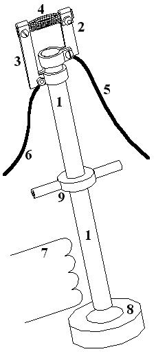
In the industry how the vibrating element, which will spray the melt metal, be possible to use a tuning fork 1, as you see
on the drawing 15.

Drawing 15.
From a crucible 2 is provided continuous feeding of the melt metal on a vibrating tuning fork. Metal plate 3 (as well as
the tuning fork, and the melt metal in crucible) are connected to a positive pole of a high-voltage source of a constant
voltage - for creation of a necessary potential difference between vibrating sparger and a substrate. The cooler 4 cooled
by a flowing liquid, is dressed on a tuning fork in a place where boughs of a tuning fork fasten to his leg (in this place
at a vibrating tuning fork there will be a node of oscillations). The constant magnet 5 which are carrying out magnetic
biasing (polarization) of the lowermost branch of a tuning fork. The variable magnetic field, which forcing to vibrate the
tuning fork, be created by the coil 6. On a surface of the upper branch of the tuning fork, which fulfill of sprinkling of
metal, is put the oxide (or ceramic) covering 7, which reduce probability of adhesion of molten metal to a tuning fork.
Probably instead of the oxide coating 7 put directly on the upper branch of a tuning fork it is possible to establish a
mouthpiece from light plate, with put already on her surface of the oxide coating. (Thin plate under action of the molten
metal more quickly will get warm, than the thick branch of a tuning fork, and we can more quickly receive of the necessary
stable temperature mode of operation of installation).
Is necessary to remind, what in the electrotechnology exist so-called "camertone generators" in which as the driving oscillator ( for determining of the oscillation frequency) using of the camertone. In our case we also can use our camertone in quality an element of the frequency standard. It always will allow to submit on the coil an electric voltage with necessary frequency - the oscillatory system will support itself in a resonance, providing the maximal amplitude of fluctuations of a branchs camertone.
For this purpose it is possible to use a capacitive coupling, see drawing 16, where the basic electroscheme is shown - one of branches of a camertone is a capacitor plate.
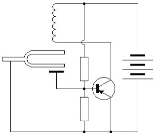
Drawing 16.
At fluctuation of a camertone be change of the capacity and then be change of the electric voltage on the transistor base. That in turn changes of an electric current, proceeding on the coil, which providing fluctuations of a camertone - there are self-oscillations. (The magnetizing the magnet on the drawing 16 is not shown.)
Also it is possible to pay attention of readers to a design of a crucible, you see drawing 17.

Drawing 17.
I shall remind, that him use for work in high vacuum. The crucible consists of two details: of the external cup 1 and of the internal 2 (inverted) cup.
The molten metal 3 pour from a crucible through the nozzle 4 under the pressure of gas 5, given in a crucible from above.
Thus, in a design of a crucible the siphon principle of work is used - it does not allow to the gas, which extrude the
melt metal 3, to leave from a crucible in the technological chamber and to poison high vacuum - only it is necessary to
not admit of full evacuation of a crucible, for it possibly use of a balance. The weight of a crucible allow to define how many the fused metal remained in crucible and to not permit his full evacuation.
Because of very high mechanical durability of the amorphous metallic alloys usual metal-cutting tools are here not be suitable.
The autogenous welding or the electric welding here also be not acceptable, since they will cause heating a metal product, and therefore there be happening the crystallization of theirs atoms, after that the products will cease to be amorphous and will lose the remarkable mechanical properties.
Perhaps, the that only two technologies allow to do a handling (the cutting) of metal products with amorphous
by structure of atoms. It: the hydroabrasive cutting of metal - a quick stream of a water,
with abrasive agent, which is weighed in her, and this a stream moving under large pressure, what will allow do cut of the amorphous
alloys, not heating up them. (The similar technology already was use on the practice - the russians diver's was
used her for cutting of holes in the hull of atomic submarine "the Kursk".) However this technology is suitable
only for rough processing (flogging) of products from the amorphous alloys. The exact operational development of
products from amorphous metals can be carried out on ultrasonic machine tools with
abrasive dust. (The similar machine tools is using for exact processing of diamonds.)
And the second, the final question is discussion of an opportunity of repeated use of the same of substrate (the of form) for multifold using in manufacturing of details from amorphous metal.
For these purposes the base sheet should be made from an usual (polycrystal) metallic alloy with high anticorrosive
properties. After how we will place the base sheet - the form in the installation and will create vacuum in the vacuum
chamber, we must make on a surface of a base sheet by simple evaporation the thin the layer of any metal (natrium or
potassium), which later we can easily dissolved in chemically active environments. And already only later it will be
possible to fill in in the form ( in the substrate) a liquid air, and make in vacuum the spitting on her a metal with
the purpose to receive a product from the amorphous alloy. After the product from metal with amorphous by structure will
be received, we may detach him off the form - substrate. For this purpose simply will be necessary to place a substrate
and product, which be glued to him, in a chemically active environment, which will dissolve a thin layer of metal between
a substrate and product from the amorphous metal alloy. Other opportunity of separation of a form (the substrate) and
product from metal with amorphous by structure, is so, what on a surface of a substrate, which previously put in vacuum,
we do ordinary way atomization of the thin layer of mercury. For this purpose the substrate will previously is necessary
to cool up to - 400 C, so as the pairs of mercury could crystallize on her surface. Later, after the product from amorphous
alloy will be made on a base sheet, will enough only allow to system: "a substrate + a product" be heating to room
temperature. Thus we will transformed mercury in a liquid phase and then will easily separate by mechanical influence the
substrate from the product, which made from the amorphous metal. (However in the latter case it is necessary to remember,
that a mercury has poisonous properties, therefore necessary accept proper safety measures, before to apply such way of
separation of products at factory.)
The method of production of the THICK products from amorphous metals, which I presented here, has been described in the application for the invention number 2003127625
(date of registration of the application in Rospatent on September, 11th, 2003). More recently I have found on expanse of the Internet the information indirectly
confirming an opportunity of realization of a method, declared by me, . It is development of the Japanese experts of the metallurgical company
"NAKAYAMA STEEL WORKS, LTD", where also was used the spatter of the fused metal, however date of a priority
at the Japanese metallurgists later - 2004.
The note: