
|
V. Tkachenko Russian magazine: "Young technician" 11 for 1992WE BUILD THE LASER |
We have got used to think that only a ruby shank is a basis of any laser. However recently also was created and the other types of lasers. One of them, can operate on the organic dyes, it is possible to construct in a technical study groups.
The diluted solution of the organic dye is irradiated with help of a self-made the trigger lamp.
The laser lets out a light ray with diameter of 5 mm, which can be focused by system of lenses. Color of a beam depends on type of dye, intensity of flash of the trigger and length of an intensifying tube.
The tube-amplifier is a basis of the laser. She is made of quartz glass, its diameter of 5 mm.
The ends of a tube are closed by two flat windows from quartz glass, and the tube is placed between two mirrors.
The second similar tube - the trigger - be mounted in parallel with the first tube. Both tubes are mounted in an elliptic reflective tubular mirror (fig. 1).
The flash of the trigger, being reflected from an elliptic mirror, concentrates on an intensifying tube because both the amplifier and the trigger are located in focuses of an elliptic reflector. Flat reflective mirrors (diameter 10 mm) are covered by silver or aluminium. One of mirrors reflects light completely, but another - only little bit more than half.
That part of light, which passed through the second mirror, and will by a ray of the laser.
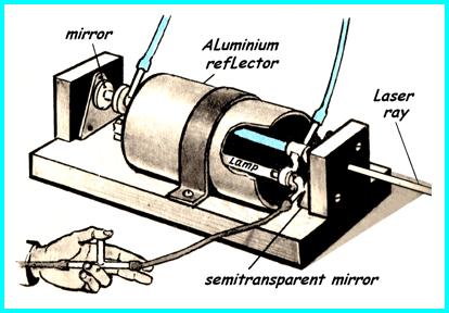 |
Fig. 1. The general view of the laser.
(The reflector showing in slit. The lamp and the amplifier are visible.) Here also Is shown connection of the vacuum pump with a trigger lamp |
The laser emission may arise only from flash of light of the big energy . How it is reached? A tube from quartz glass with electrodes from stainless steel or copper and filled by the air is it and be the trigger.
This electrodes join to electric cleats of the condenser with electric capacity in 15 mf with potential of a electric charge , approximately 3 thousand volts. For start of the trigger it is necessary to create in it underpressure in 60 mm of a mercury column. As soon as pressure will fall up to the necessary size, the condenser will be unloaded and there will be a flash of the laser.
Before the next impulse of the laser the amplifier should be cooled up to a room temperature. For this purpose the solution of dye continuously proceeds through an intensifying tube.
To the ends of the intensifying tube we put on and paste glue with help of the glue "BF-2" of the cupric bringing tubes.
Transparent quartz windows paste to ends of the copper tubes. Speed of watercourse of a solution of dye should not be less than 4 litre/hour.
We can do of the underpressure of air in the trigger by means of the manual vacuum pump (or electric if you have he).
The ending branch pipe of the pump should be shipped in bank with the suds (soap water), is better in a solution of a detergent powder.
It is necessary because the air, in room where the laser works, has not been polluted by the pairs oils. Any pollution of the alcoholic solution of dye will not allow to get out of the laser even a hint on a light ray.
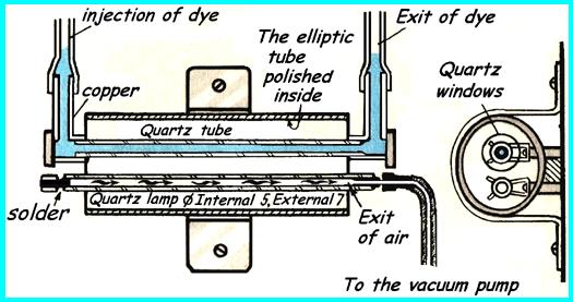
| Fig. 2. The laser in a cut
Pay attention to an arrangement of a lamp and the amplifier in focuses of an elliptic reflector |
 |
The trigger begin work so: in the rubber tube going from a trigger lamp to the vacuum pump, be inserted the T-shaped glass or metal tube. At the time of work of the vacuum pump the air will come through the open end of the T-shaped tube. But if densely to block an orifice of a T-joint by a finger, then the pump will start to pump out air from the trigger.
The electrodes of the trigger lamp are made of copper or stainless steel. Diameter of an internal part about 8 mm, and the ends are rounded off and we can polish theirs.
The lamp-trigger and the amplifier are mounted strictly in parallel on distance of 15 mm from base - plates from plastic or thick plywood. Distance between axes of a lamp and the amplifier of 12 mm.
The reflector represents the thin-walled aluminium tube in length of 80 mm and internal diameter 25 mm. Its internal surface should be well polished. Then the tube should be cautiously squeezed in a bench screw so, that she became elliptic in section. The greater axis of an ellipse should be longer on 3 mm as compared with a small axis. We need carefully adhere to these sizes. The reflector we fastens to the basis with help of a metal yoke. The greater axis of an ellipse is located in parallel of a flatness of the basis. In focuses of an ellipse (distance between them of 12 mm) are fixed the trigger and the amplifier (fig. 2). The axes of tubes should strictly coincide with focuses of an elliptic reflector. Cells for fastening flat reflective mirrors and adjustments of their parallelism are showing on fig. 3. Adjusting screws with the metal springs serve for adjustment of a corner of a meeting of a ray with a mirror. The semitransparent mirror is directed by the silvered surface to of the intensifying-tube. This mirror we can make so. We carefully degrease the glass plate, cover on the one hand nitro dye and do with it reaction of the silver mirror known from a course of chemistry. It is important to define retention interval of glass in a reactionary solution, when the layer of silver has turned out semitransparent. It may be reached cleanly experimental: the 5 small fragment of glass we put in the it vessel with a chemical solution on a different time.
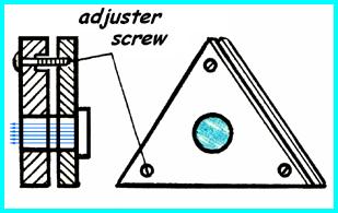 |
| Fig. 3. A cell for fastening reflective mirrors
and adjustments of their parallelism |
It is desirable, that through the mirror go about 18 % of light. It we can check by means of luxmeter.
The power supply of the trigger is mounted in a box under the basis on which are fixed an elliptic reflector, the trigger and the amplifier.
The wires from the condenser to the trigger should be as it is possible more shortly and to possess the minimal resistance to reduce duration of the capacitor discharge because intensity of the beam which is let out by the laser, depends on duration of flash. Is better to use copper wires, which have cross-section 10х1 mm.
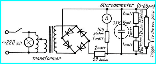
The scheme of the power supply of the trigger (fig. 4) is clear enough and will not cause difficulties at installation.
|
| Fig. 4. The module of the power supply |
In the laser the several dyes can be used. For initial experiments it is better to take rhodamine. This orange paint allows to receive a beam of the laser from yellow-green up to red color. For preparation of such chemical solution we need to add 45 mg of rhodamine in the 1 litre of the methyl alcohol.
The interesting dye which emiting a ray of intensive blue color, is diethylaminomethyl-coumarin. For it we need 75 mg of this paint on a litre of the methyl alcohol.
The fluorescein sodium is used in concentration of 45 mg on litre of ethyl alcohol.
The ready laser demands one, but very responsible adjustment: it is necessary to establish flat reflective mirrors of strictly perpendicularly axis of the amplifier and strictly in parallel with each other. Otherwise the laser not will work . For installation of mirrors we need have the pocket flash-light, the field glasses or a spyglass, but is better a school telescope. It is necessary to have also two prisms, representing in section an isosceles rectangular triangle. In each the field glasses four such prisms is. On glass of a lamp the diaphragm from an opaque material with a dot outlet against an incandescent filament of a lamp is pasted. At first we must remove the semitransparent mirror, the other devices in that time be as shown on fig. 5. in upper part. In the objective of a telescope will appear two images of an incandescent filament of a electric lamp.
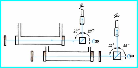 |
Fig. 5. Adjustment of the laser.
On the upper part of figure the semitransparent mirror is removed. Adjustment of position of an opaque mirror is made. The below on figure is shown the course of rays in system at adjustment of position of a semitransparent mirror. |
Both images (and refracted by a prism, and reflected by an opaque mirror) we must unite, and it need be made so, that the combined image will precisely in the middle of a field of vision of the field glasses, a spyglass or a telescope. Next we established the semitransparent mirror (lowermost part fig. 5), and then the double image of an incandescent filament (reflected by a semitransparent mirror and which was received earlier overlapping) necessary again combined. In this case it is necessary to do adjustment of installation only of a semitransparent mirror. When all this is made, your laser is ready to work.
(Translation into the English language has executed A.J. Streltsov.)